
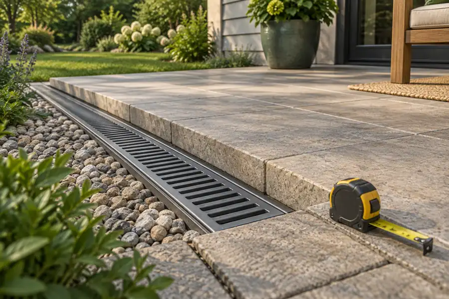
A channel drain order starts with a route and a discharge point, not a guess at how many grates fit across the patio. Measure each straight run, choose the exact channel system, and count the corners, outlets and end details separately. Then turn those measurements into whole sections and packs.
The channel drainage calculator handles that quantity work. It doesn’t decide how much runoff your property produces or whether an outlet can accept it. Those questions come first: a neatly measured drain still needs a suitable destination for the water.
Sketch the whole route before measuring the straight pieces
Mark the surface that sheds water, the proposed channel, changes in direction, access points and the onward pipe. Give every straight part a name. A quick sketch marked “patio edge” and “garage return” is easier to check against a quote than one unexplained total.
Measure the length that straight channel bodies actually occupy. A separate corner or sump may take up part of the route. Subtract that occupied length using the supplier’s drawing before entering the straight run; the calculator cannot infer every manufacturer’s fitting dimensions.
Keep the endpoint level and the outlet connection on the sketch. NDS’s channel-drain planning guidance identifies loading, drainage capacity, outlet configuration and installation conditions as selection factors. Use those factors to narrow the product before finalizing your list. A driveway crossing and a pedestrian patio edge are different applications.
A worked order: two 10-foot runs
Suppose there are two independent straight runs, each 10 feet long after fitting allowances. For this arithmetic example, the selected channel has 3 feet of effective installed coverage per section and is sold individually. These are illustrative product dimensions, not a named product recommendation.
Each run needs 10 ÷ 3 = 3.333 sections, rounded up to four. Across the two runs, buy eight sections. That gives 24 feet of purchased coverage for 20 feet installed. Each run uses three full sections and 1 foot of the last section, subject to the product’s permitted cutting locations.
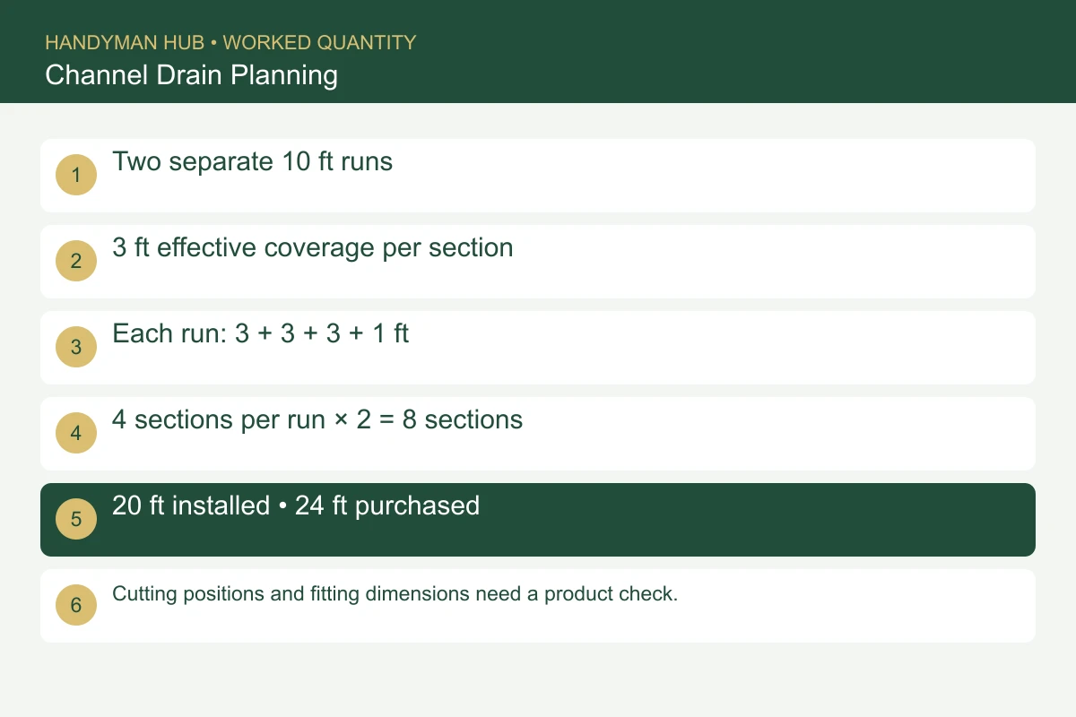
Combining the lengths first would give 20 ÷ 3 = 6.667, or seven sections. That lower answer assumes useful sharing of cut pieces between runs. The live calculator rounds each run independently; it doesn’t promise that an offcut retains the correct connector, end detail or cutting position. A supplier may approve a more efficient layout, but it should be shown on the cutting list.
To reproduce the example, choose Imperial measurements, enter a 10-foot run with two identical copies, and set effective section length to 3 feet. Leave spares at zero and pack size at one. The section requirement is eight. If your supplier sells two sections per pack, the same requirement becomes four packs. Enter the price per pack, not per foot.
Count fittings by their job
A run card isn’t an automatic instruction to buy two end caps. Several straight lengths may join into a single route, and an outlet may replace a closed end. Label the actual termination at each end: cap, outlet, corner, junction or access unit.
Write down separate quantities for corners, T junctions, outlets, sumps and any connectors the chosen system requires. Check whether matching grates are included with the channel price. If they are, leave the separate-grate option off. If not, confirm the grate’s effective coverage and pack size; straight grates also round by run.
An internal joint count is useful for checking the layout but isn’t automatically a connector purchase count. Some systems clip together. Likewise, a fitting may need its own cover even when every straight channel comes with a grate. Ask for a complete component schedule, rather than assuming a kit covers every detail on your sketch.
Keep concrete and excavation as separate quantities
Once the installation detail is selected, enter its concrete dimensions. The calculator’s rectangular model counts a bed beneath the channel and two side strips above that bed. For an illustrative section with a 6-inch-wide channel, 3-inch side strips, a 4-inch bed and 6-inch side height above the bed, the concrete area is (6 + 3 + 3) × 4 + 2 × 3 × 6 = 84 square inches.
Over 20 feet, that is 84 ÷ 144 × 20 = 11.667 cubic feet, or about 0.432 cubic yards, before separately assessed end details and reserve. These dimensions demonstrate the formula only. Use the exact manufacturer’s detail for your loading and ground conditions; don’t build a surround from this example.
The excavation total uses the full trench width and depth you enter. It isn’t the same as concrete volume. If soil removal is part of the job, use our bank-volume and loose-spoil guide to keep those bases separate. The concrete ordering guide explains finished bag yield and ready-mix rounding.
What to send with the supplier enquiry
Send the dimensioned route, selected product, application, proposed outlet and a marked component list. Include grate requirements, permitted cutting positions and the installation drawing used for the concrete estimate. Record delivery, pipework, excavation, disposal and reinstatement separately so that two quotes cover the same job.
Before ground disturbance, follow your state’s process through 811 and identify any private services that need separate locating. Confirm the discharge arrangement with the relevant local authority or drainage professional rather than assuming water can be sent to the street or a neighboring property.
Finally, run the channel drainage estimate with the supplier’s actual pack sizes and prices. Keep the printed result with the sketch: the numbers explain the order, while the sketch explains where each piece belongs.
Featured image: original concept illustration, not a completed Handyman Hub customer project.