
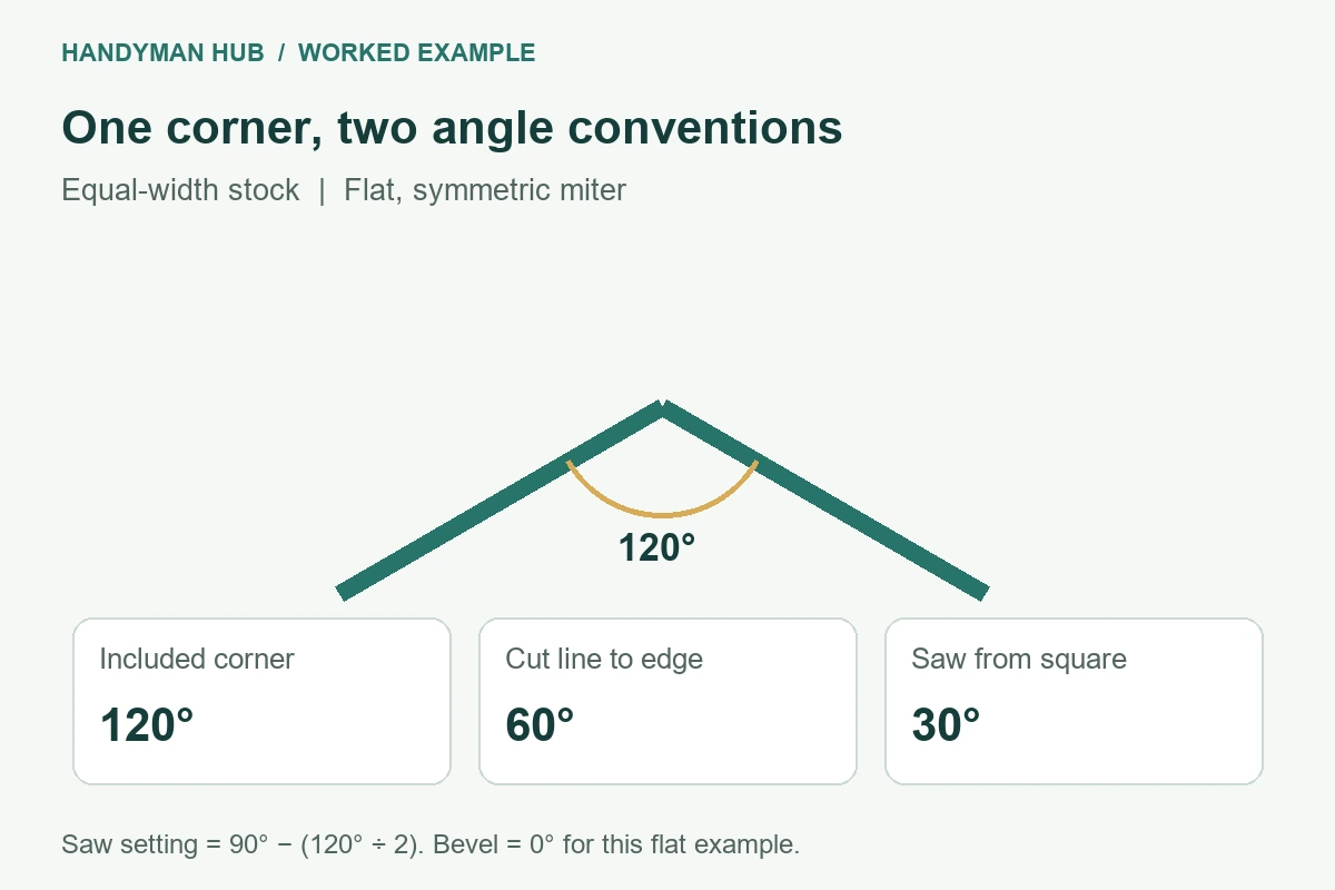
A corner measures 120 degrees, but the miter saw needs a 30-degree setting. That is not a contradiction: the protractor and the saw are measuring from different reference lines.
This guide explains the geometry for two equal-width pieces meeting in a flat miter. Use the miter and corner angle calculator to check the numbers, then verify the orientation on scrap before cutting the finished trim.
Identify the angle you actually measured
The included corner angle is the angle between the two directions the pieces follow. A square corner has a 90-degree included angle. A wider, open corner might measure 120 or 135 degrees.
A standard miter-saw scale reads zero for a square crosscut. Its number describes rotation away from that square position. Meanwhile, the angle between the cut line and the long edge of the board is 90 degrees at that same zero setting.
That difference is the source of the confusion. Jesper Cook’s explanation in THISisCarpentry illustrates the distinction between protractor readings and miter-saw settings. Check your own saw’s markings and manual rather than assuming every displayed scale uses identical conventions.
The 120-degree corner worked through
For an equal-width, symmetric flat joint, bisect the 120-degree corner. Each cut line lies at 60 degrees to its piece’s long edge. Because the saw reads from square, subtract that 60 from 90: the setting is 30 degrees.
In the live calculator, choose the smaller included-angle convention and enter 120. The checked output gives a 30-degree miter-saw setting, a 60-degree cut-line angle, a 120-degree included corner and zero bevel.
The two pieces need complementary left/right orientations. The result gives the setting’s magnitude; it does not decide which side of the blade to keep, which face belongs upward or which end of the workpiece forms the joint. Mark those choices directly on the offcuts.
A short comparison table
| Included corner | Cut line to long edge | Saw setting from square |
|---|---|---|
| 90° | 45° | 45° |
| 120° | 60° | 30° |
| 135° | 67.5° | 22.5° |
| 150° | 75° | 15° |
| 180° | 90° | 0° |
The general expression is saw setting = 90° − included angle ÷ 2. As the corner opens toward a straight line, the saw setting gets smaller. At 180 degrees, the geometry becomes two square ends meeting along a straight run.
An acute corner can require a setting beyond a particular saw’s normal range. The numerical answer does not extend the machine’s capacity. Do not improvise an unsupported workpiece position to reach it; follow an appropriate method and the equipment’s instructions.
Inside, outside and reflex readings
An angle finder may let you read around the other side of the corner. That larger reflex angle exceeds 180 degrees. Its corresponding smaller included angle is 360 degrees minus the reflex reading.
For example, a 240-degree reflex reading corresponds to the same 120-degree smaller angle used above. Select the correct convention in the calculator, rather than entering 240 into a field that expects the smaller angle.
“Inside corner” and “outside corner” are also installation descriptions. They affect which edges are long, how the trim is oriented and whether a miter is the right joint for the job. They do not remove the need to identify the measured angle convention first.
Angle and finished length are separate checks
A correct saw setting can still produce a piece that is too short. A mitered end has a long point and a short point. State which point your length references, and use the same convention in the drawing, cut list and marks.
Keep the keeper side and waste side visible. Blade width matters when locating the cut relative to the mark, even though it does not change the theoretical angle. If the material has a profile, label its top or exposed face so the second piece is not accidentally mirrored the wrong way.
Test the pair against the actual corner with scrap of the same relevant section. A flat sketch cannot show a bowed wall, a twisted board or a corner that changes angle through the height of the trim. Check the fit before committing all matching pieces.
When this simple formula is not enough
Crown molding cut flat, compound joints and pieces tilted out of the reference plane involve bevel as well as miter geometry. Unequal-width stock may need an unequal split for matching edges. Do not treat this equal-width flat-joint calculation as a general solution to those cases.
For a wider project, use the lumber calculator after the finished lengths and end references are settled. Decorative members within the frame can be laid out with the equal spacing calculator. If the frame surrounds sheet material, the sheet cutting planner helps check the panel purchase separately.
Related project planning
A neighboring finish may need its own reference lines. The tile centerline and edge-cut guide explains how another trade establishes a balanced layout before cutting. Coordinate visible alignment where it matters, while keeping the tile joint and wood miter calculations separate.